You will learn in this post, what is and how the current transformer (CT) works, CT burden resistor calculation with examples, applications of CT transformer, types, tests, etc.
The content of the post is as follows
What is a current transformer?
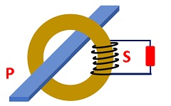
A current transformer (CT) is basically an instrument transformer and produces the current in the secondary proportional to the primary current of the transformer.
It produces the electric current in the secondary regardless of the load or burden value but within its working range of the load.
Further, the current magnitude in the secondary is less than the primary.
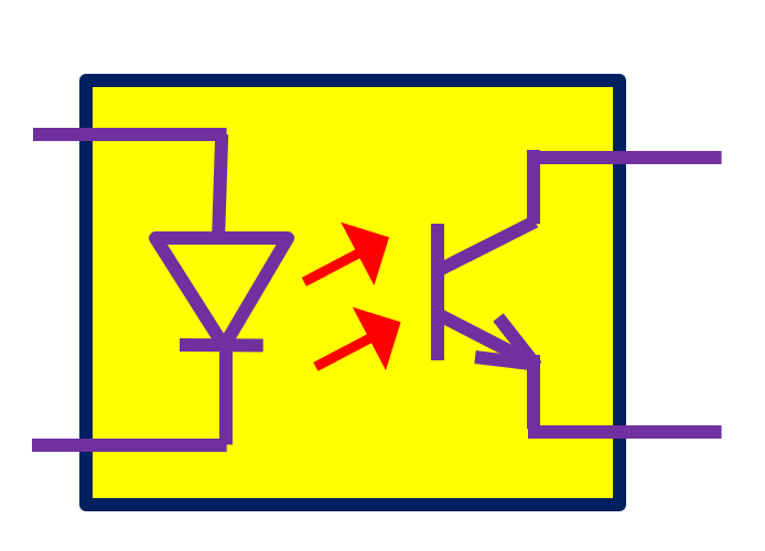
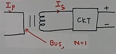
The current transformer is also called “CT” which is a short form of it. Refer the figure 1 for the symbol of the CT.

How the current transformer works
The current transformer works similarly to the normal transformer. But the method of a sequence of calculation is different.
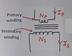
Generally turns in the secondary of the CT are more than primary turns. As the secondary turns are more, so the secondary voltage will be more, but the secondary current will be less than the primary.
We call it step-down CT as the secondary current is less than the primary in the current transformer. But it is nothing but a step-up voltage transformer. As voltage is more and current is less in the secondary compared to the primary voltage and current.
CT burden (maximum) and current ratio calculation example
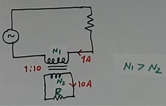
Now refer to figure 3 for a discussion on CT burden. The secondary to primary turn ratio is 10 as an example. This means that turns in the secondary winding are 10 times the turns in the primary.
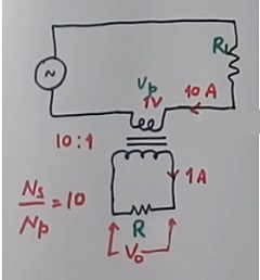
So voltage in the secondary is 10 times more, but the current in the secondary is 10 times less than the primary current.
For example as in the above circuit, if the primary current is 10 amperes then the secondary current will be 1 amp (10 times less than the primary).
In the CT, we calculate the current first (not the voltage first). As in the above example, if the primary current is 10 Amps then the secondary current will be 1 amp.
Then, we will calculate the voltage in the secondary. The voltage in the secondary will be equal to the current multiplied by the load resistor (Burden resistor). Note that the current remains 1 Amp in secondary for all the load resistors.
Refer to figure 3. I will calculate the secondary voltage as follows, The current in the secondary is always 1 ampere.
- For a 1-ohm (burden) load output, the output voltage will be 1X1 = 1 volt
- For a 10 ohm resistor, the output voltage will be 10X1 – 10 volts
- For a 100 ohm resistor, the output voltage will be 100X1 = 100 volts
- For a 1K (1000 ohms) resistor, the output voltage will be 1000X1 = 1000 volts or 1 kV
You see that as we are increasing the burden resistor value at the secondary, the output voltage is increasing. If we increase the resistor value further, or if the secondary opens, then a very high voltage will come.
So there is a limit of resistor value, which can be connected at the secondary. And CT output should not be open.
This maximum resistor value is called the maximum burden on the CT.
What is the maximum burden in CT – Calculation
In the above example, if the VA rating of the CT is 10 VA (it is assumed). The maximum voltage can be 10VA/1A = 10 volts.
This 10-volt at 1 A output corresponds to a 10 ohms resistor. So in the above case, the maximum resistor value allowed is 10 ohms (for a 10 VA CT).
And the primary voltage will be just 1 volt at a 10-ohm resistor load.
Equivalent circuit of current transformer
Now, refer to figure 4. This shows the basic magnetic core circuit. This is similar to any transformer.
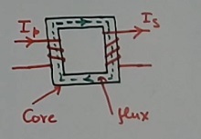
The flux in the above circuit flows in the core. This flux is shown as the equivalent magnetizing current IM.
Refer to Figure 5. It shows the equivalent circuit of the current transformer. This circuit is also similar to any transformer.
When we draw an equivalent circuit, we do not show separate primary and secondary winding equivalents generally. We show every component value corresponding to the primary side.
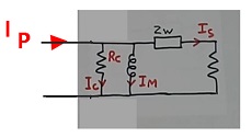
The losses in the transformer are shown with equivalent resistor RC and current IC in the above circuit. The ZW is the equivalent impedance of the transformer.
The IS is the secondary current but shows the primary side. To make it clear, 1A is the secondary current IS in figure 3. But in the equivalent circuit, IS will be 10 amps in figure 5.
Applications of the current transformer
The applications of the current transformers are as follows:
- summation of the current
- current measurement for controls
- power supply at high voltage
- protection
- isolation
- metering
- power measurement
Summation CT
The summation CT is a special type of CT. Refer to figure 6. It has two primary windings and only one secondary winding. The current in the secondary will be the summation of the currents in both the primary windings. The CT ratio will still be maintained.
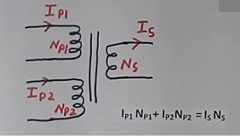
The summation of the ampere-turns ( IxN) of both the primary windings, is equal to the ampere-turns of the secondary winding. The formula is as follows
IP1 NP1 + IP2 NP2 = IS NS
I used the summation CT in one of our projects to add the current from the two different electric arc furnace loads. This arrangement does not require any additional summation amplifier also.
Current measurement for control applications
If we are using the current transformer for the control application, then we need to calibrate it. This calibration is done to make the measurement accurate.
Figure 7 shows the concept of calibration. The voltage of the secondary of the CT is given to the input of an amplifier with variable gain. The gain of the amplifier is adjusted to get the correct value of the output corresponding to the primary current.
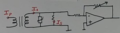
This may be required due to a deviation in the current ratio of the CT.
A Transzorb is connected at the secondary of the CT for surge voltage suppression.
Power supply at high voltage application of CT
Generally, we make the power supply using an AC voltage input. However at a very high voltage level (say 100 kV or 220 kV), no such voltage is available easily, We have only the current flowing in the wire, and we need a power supply for electronics in certain applications.
In such cases, we can make a DC power supply from the current itself. Refer to figure 8. The detailed concept of this is not within the scope of this article.
We needed this type of supply in some of our big projects.
Types of the current transformer and construction
Wound-type current transformer:
This type of CT is like a normal transformer with one core and two windings over the core. Refer to figure 9.
Bar type CT:
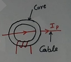
In the bar-type CT, the core will be generally round type. Refer to figure 10. There is one secondary winding, but it has no primary winding.

There is a copper or aluminum bar, which acts as a primary winding. It is similar to one turn in the primary winding. This bar is part of the CT.
This arrangement is useful if the primary current is very high.
Window type CT:
The window-type CT is similar to the bar-type CT as above, but no primary winding, not even a bar.
The actual wire having the main load current itself passes through the core and behaves as a bar or one winding of the transformer. This is a very common type of transformer.
Typical specifications of the CT
The specifications of a typical current transformer (CT) are as follows as an example
- System voltage – 11 kV
- CT ratio – 100/1 amps
- VA rating or burden – 10 VA
- Frequency – 50 Hz +/- 5%
- Accuracy – class 1
- Ambient temp. – 70 degree
- Short time current rating – 20 kA for 1 Sec.
- Standard – as applicable
- Type – Window type
- Indoor/Outdoor – Outdoor type
- Cooling – Natural cooling
- Terminal types
- Tests
- Any special requirements
Typical tests on the CT
Some of the routing and type tests done on the current transformer are as follows
- Accuracy test
- Dielectric insulation test
- temperature rise test
- Short-time current rating test
- Terminal marking and polarity
These tests are done as per various standards.
Extra knowledge as per experience
As I said above, the current transformer is similar to the voltage transformer. The voltage ratio and current ratio formulas are also the same.
But we do not use a CT as a voltage transformer or vice versa. This is due to the fact that the current and voltage rating of the primary winding is different for the CT and voltage transformer.
The CT connected to the high voltage has generally just one turn in the primary, which can take a few volts only. As the primary voltage of the CT is just a few volts, it hardly has any use as a voltage transformer.
The CT is also designed to give a more accurate current ratio than the voltage ratio. (Note the formula of voltage ratio equals to turn ratio is just theoretical and has too much error practically).
To understand this watch read my article on the potential transformer.
However, if you use any transformer within current and voltage limits, then you can always use CT also as a voltage transformer for some development works or knowledge.
Open output in CT
As per the earlier calculations explained, if the CT output is open then the very high voltage at the output may come.
However, this is just a theoretical concept. As the core will saturate at a much lower voltage. So. the very high voltage in the secondary is always limited due to the core size point of view.
To learn more about open circuits, read how to use an open-circuit CT transformer.
Step-up current transformer
I discussed all step-down CTs. But sometimes we need step-up CT also.
I myself required a step-up CT for testing my control panel on an analog simulator at a simulator testing center. As the simulator had a less current rating, a step-up of current was required.
Then I used step-down CT in reverse to make it a step-up CT transformer. Refer to figure 12. This current transformer is exactly the same as shown in figure 2 but connected in the reverse mode.
With the above method, I could amplify the current 10 times. However as the current transformer was tuned for step-down, it will give errors in step-up use. But we used it just for testing purposes only.
Destruction of the current transformer
I have told above under para of CT specification, that short time current rating is 20 KA for 1 second as an example.
If you test the CT for this current, the CT will look like passed. But that is not correct.
In one of our type tests of CT, we did this test. Then the core of the CT is cut. This means that the CT is destroyed and can not be used again (and that was an expensive CT).
After cutting the core, it was checked by some experts that the orientation of the iron particles in the core remains the same and is not changed or damaged.
After that only, the design and manufacturing were approved as per IS standards. Further, we have to order another CT for our use.
For detailed information watch the Current transformer concept
Further, read about Potential transformers.
Also, read about the SMPS transformer.
Further, read the Difference between CT and PT transformers.
Continue learning and read Why is a 30 mA RCCB breaker used?
Further, read about neutral earthing in the transformer.
I hope that you enjoyed the article on How CT transformer works and CT burden calculation.
If so, then subscribe to my YouTube channel.
About the author – G K Agrawal B.Sc and B.Tech (from HBTU Kanpur), Retd. Sr DGM Design (BHEL), the inventor of patents, has lifelong industry experience in the electrical and electronics design field of R&D. He worked for BHEL. He shares his experience and knowledge on blogs and YouTube. Read the profile here.