
In this post, I discuss: why “power factor correction” and its method, the causes and problems of low power factor, and how to correct power factor and its advantages. You will also learn fixed step type and continuous variable PF correction, the need for fast correction (SVC), and the need for an extra inductor.
I will also discuss extra knowledge as per my industry experience of designing such control equipment.
“The power factor correction is done to reduce voltage variations, reduce penalty and energy loss, and also to improve the transmission capacity of conductors. This is also called power factor improvement”. There are many more advantages of power factor correction (PFC) discussed in this article.
As this is a big article, so content is given below as follows:
What are the causes of the low power factor?
The main cause of the low power factor is the flow of the reactive power in the system due to the presence of an inductor in the electrical circuit.
However, there are many causes of low power factor as follows:
- The inductor load in an electrical circuit
- Inductor due to transformer impedance
- Unbalance active load (this requires an unbalanced power factor correction system)
- Triggering thyristor in AC to DC conversion
- Motor load
- Electrical welding equipment
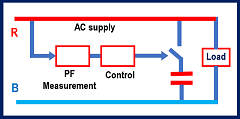
Figure 1 shows a simple electrical circuit diagram just for an explanation of the causes of the low power factor. The power supply comes from a power station to the substation using a transmission line. Then from the substation power, the AC supply goes to the load and also to the other electric circuit.
The load has both the resistor and inductor. As the load is an inductor, reactive power flows in the circuit.
The flow of the reactive power (due to inductive load) reduces the power factor of the electrical system.
A low power factor means that reactive power or reactive current is flowing in the electric power system.
If reactive power is zero then the power factor is unity and best. The reactive power present in the system reduces the power factor to less than one. And we call it low power factor.
In this article, I may use the word reactive power reduction in place of the power factor correction many times.
What are the problems with low power factor?
A low power factor creates problems like voltage drop or variation in supply, energy loss in the conductor, and reduced active power transfer capacity of the transmission line and also of the transformers and also penalty on the industry.
Further fast variation of the reactive power (or power factor) if any, creates a flicker problem in the lighting system.
Benefits of power factor correction
Power factor correction is necessary and there are the following benefits of power factor correction:
- It reduces the voltage drop and voltage variations
- It improves the power transfer capacity of the transmission line
- It reduces energy loss in the conductors
- It reduces PF penalties in the industry
- IT reduces flicker in the steel industry
Whenever we connect an inductive or any other load, then electric current flows in all conductors from the power station up to the load. And the length of this conductor will be too much, especially for lines from the power station to the substations.
These conductors of transmission lines have resistance and inductance.
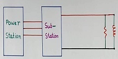
Refer to Figure 2. I have shown the resistor and inductor of the transmission line in one place only for explanation.
This resistance and inductance represent the resistance and inductance of the conductor and transformers of the full line from the power station up to the load.
Actually, these resistors and inductors will be distributed all along the transmission and distribution lines. But it is shown in one place for explanation purposes.
Now the reactive power (or current) in the load inductor will also flow in the entire transmission line. This means that this reactive power current flows in the line resistor and inductor.
1 – The Power Factor correction reduces voltage drop and voltage variation
As per the above discussion, This current (of inductive load) will flow in the transmission line, so it creates a voltage drop across the resistor and inductor of the transmission line and transformers.
So there will be a voltage drop in the transmission line and transformers. This voltage drop will change with load variations. So there will also be voltage fluctuation in the power line voltage at the load point.
This voltage variation and reactive power are not required at all. So if we improve the power factor or do power factor correction, (reduce the reactive power flow), then this unnecessary current can be avoided. And so voltage drop and voltage fluctuation will be less.
The voltage drop also occurs due to resistive load, but that will be less. The voltage drop due to inductive load is much more in the transmission line.
So “power factor” correction or improvement will considerably reduce the voltage variation of the AC power supply in the industry.
2 – PF correction improves the transmission line capacity
If we remove the unnecessary reactive current by power factor correction, then we can connect the more useful active load.
And so, the effective power transfer capacity of the transmission line in the power system will increase. As we can use it up to the maximum possible active load.
3 – PF correction reduces energy loss in the conductors
Further, the current flowing in the inductive load will also flow in the resistor of the transmission line. By improving the power factor, this unnecessary current is reduced in the transmission line.
So energy loss in the conductor of the transmission line is also less. So there will be savings in energy, even if it is on a small scale.
4 – PF correction reduces the penalty in the industry
Many electricity boards put a penalty on the industry for low power factor. If the power factor goes below some set value say 0.9 (for example) then the industry has to pay a penalty for that. Generally no penalty for low power factor at home.
This encourages the industry to install power factor correction equipment.
5 – Fast Power Factor correction reduces flicker in AC supply in the steel industry
The PF correction equipment is installed for technical reasons. The flicker in the steel industry is one such example. The steel industry has an electric arc furnace load.
And the PF correction equipment (SVC) required for the steel industry is quite a fast correction type.
Read further about this in the last part of this article in the extra knowledge as per experience.
How to do the power factor correction
Power factor correction (PF correction) is achieved by reducing this reactive power in the electrical system.
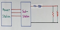
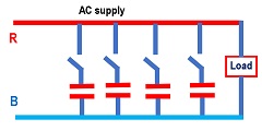
The power factor can be corrected by installing capacitors across the load as per the circuit arrangement in figure 3. We call it a capacitor bank.
These capacitor banks draw the current at the 180-phase shift of the inductor current. So the electrical current drawn by the inductive load is canceled by the current flowing in the capacitors.
So the net reactive power flow reduces and the power factor improves.
Methods of Power Factor Correction
There are two methods for the connection arrangement of capacitors.
- Fixed PF correction capacitor bank
- Continuous PF correction
Fixed and step-type PF correction capacitor banks
In this case, many capacitor banks are installed. Then we switch “ON” the necessary number of capacitor banks one by one as per load requirement.
This is done automatically by the power factor correction panel. I will discuss this in detail further in this article.
Continuous PF correction (SVC)
In this case value of the net capacitor in the PF-correction equipment is controlled continuously.
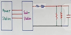
We use a fixed capacitor as well as an additional inductor to achieve continuous power factor correction (or reactive power reduction). Refer to figure 4.
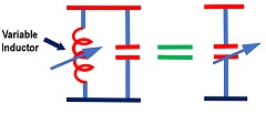
The full fixed capacitor will remain “ON” always regardless of the load requirement.
Then we control the value of the inductor using continuously controlled thyristors. The value of the inductor current will be zero for the maximum capacitor in the circuit.
Further, the value of the thyristor-controlled inductor will have the necessary electric current to reduce the effective value of the capacitor. We call it a static VAR compensator (SVC) system.
The VAR compensator(SVC) is also used to stabilize voltage in the power transmission system (high voltage AC supply).
How does power factor correction equipment work
The power factor correction (PFC) equipment works on the concept of the closed-loop control system. The equipment has many capacitor banks of small ratings.
Refer to Figure 5 for the concept block diagram for the power factor correction (PFC) equipment. Only one phase RY is shown in the figure. But capacitors will be in all three phases. The power factor controller will be single for all three phases.
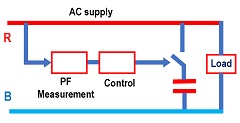
It measures the power factor of the system, and as per requirement, it switches “ON” or switches “OFF” capacitor banks.
Further, this figure has only one capacitor bank. But there will be many capacitor banks in the system. Refer to figure 6.
The switching ON and OFF of the capacitors takes place in sequence and one by one capacitor bank.
The required power factor can be set in the controller in the control panel. This set power factor value will be less than one to avoid over voltage in case of sudden reduction of the inductive load. As controller will take some time to switch OFF the capacitor due to its slow correction process.
This kind of PF correction panel is the slow type and may take a few minutes to switch ON all the capacitors banks for technical reasons like allowing capacitors to discharge through a bleeder resistor.
The switching power device may be a contactor or a Triac. The use of the Triac reduces the surge current in the capacitors during the switching process.
Further many times, this kind of PF correction panel is supported by a pre-installed fixed manually switched capacitor bank. This is to reduce the cost.
Capacitor bank “ON” and “OFF” sequence
This switch sequence of the power factor correction capacitor banks also follows the first “IN” and first “OUT” concepts.
This means, if we want to switch OFF one capacitor bank, then that capacitor bank that was switched ON first, will be switched OFF now.
Need of extra inductor in capacitor
Generally, a very small inductor is connected to a series of capacitors. This is to avoid a high peak surge current in the capacitor during the switching process.
This inductor may be used even if Triac is used for switching purposes.
This inductor value is selected considering the possible resonance in the system.
Extra knowledge as per experience
In the above discussion, I always talked about PF correction in the industry. I did not mention PF correction in the homes. There is a reason for this
Why no PF correction in the home
The load at the home is much less compared to the transmission line capacity. So PF correction at home hardly makes any difference until otherwise, PF correction is done in all the homes.
Further, installing PF correction equipment in all homes has many practical and financial implications.
A common PF correction equipment for all the home load is more practical and economical. This can be handled by the electricity board itself as they have expertise also.
PF correction for the steel industry
Many steel industries use ARC furnaces for melting raw materials. It works like a welding machine. So occasionally the three-phase electrodes will get short and heavy current flows in the system.
Further, the variations in the load current are very fast. This will cause voltage variations in the AC supply.
If this load current variation (RMS value) is in the range of 5 to 10 Hz, then the voltage variation (RMS value) in the AC supply also will be of the same frequency.
And this frequency is very painful, as this causes flicker in the lighting system. This is due to the fact that our eyes are very sensitive to the 5 to 10 Hz frequency range.
In one of the steel plants, this problem was so great that flicker in light was happening in the entire city located 20 km away from the steel plant. As it was a very big ARC furnace.
This requires a very very fast reactive power control system (a kind of PF correction equipment). We call it a static VAR system (SVC) in technical terms.
Note that even if we call it power factor (PF) improvement or PF correction, we actually measure and control reactive power and not the power factor in this steel industry example.
However, reducing reactive power in the system directly improves the power factor. This is applicable to large-size SVC systems.
After installing such equipment, the flicker problem could be avoided.
However, nowadays, this problem is less as we use LED now and the LED lighting system has a built-in regulator inside the choke.
Unbalance load problem in the ARC furnace
In the above case of the steel industry, this is also possible that only two electrodes of two phases in an arc furnace become short. In such cases, too much unbalanced current will flow.
Further any unbalanced active load like in an arc furnace causes low power in different phases. This requires an unbalanced power factor correction system.
This will cause unbalanced voltage and then heating of the induction motor due to this unbalanced voltage.
This requires different values of reactive power or power factor correction in different phases. We call it an unbalanced reactive power control system.
Balance power factor correction for unbalanced load
In one of the steel mills with an arc furnace unbalanced load, we supplied balance reactive power control (PF correction) type equipment. This is because, if the power supply system is very strong with a high short circuit level compared to the load, then the unbalanced voltage variation will be less.
So the power factor correction equipment is not for just power factor correction, but also for a few more technical reasons and functions.
Watch the video on power factor improvement
Also, read what is wind power.
Further, read How bullet train works?
Also, read How to use open circuit CT transformer.
Further, read the difference between power factor and reactive power.
I hope that you enjoyed the article ” Low power factor correction, causes and how to improve it“.
If so, then subscribe to my YouTube channel.
(Note: the author has worked with BHEL as one of the technical leaders in designing the many power factor correction (also SVC) equipments of rating from a few 100 KVAR to 100 MVAR for various applications)
About the author – G K Agrawal B.Sc and B.Tech (from HBTU Kanpur), Retd. Sr DGM Design (BHEL), the inventor of patents, has lifelong industry experience in the electrical and electronics design field of R&D. He worked for BHEL. He shares his experience and knowledge on blogs and YouTube. Read the profile here.

Very detailed explanation
Magnificent site. A lot of helpful info here. I?¦m sending it to several pals ans additionally sharing in delicious. And certainly, thanks in your effort!