
You will learn the difference between the power factor and reactive power in this post. We will discuss active power, reactive power, apparent power, and “power factor” and also the formula of correlation between them with a calculation of power factor and examples. And also as usual extra knowledge based on my industrial design experience.
The table of contents is as follows:
The power factor depends on active power and reactive power both. So first we will explain, what is active power and reactive power.
There are three main load components, resistor, inductor, and capacitor in an electrical circuit. The type of power depends on the type of load. We will discuss them one by one now.
What is active power?
Active power is the power consumed by the load. It is measured in kW or watts. This power is consumed by the resistor or some mechanical work and converted to heat energy and lost. This is useful power to do the work.
This active power is equal to the current (RMS) multiplied by the voltage (RMS) across the resistor. We denote this active power as “P” generally.
Active power P = Voltage x Current = V X I (watts or kW)
What is reactive power?
The reactive power is the power flowing in an inductor or capacitors and is measured in kVAR or VAR. We say that reactive power is flowing. This power is not consumed by the load. This power goes back to the AC power supply.
So the power flows from the AC supply to the load and then goes back to the AC supply. This process continues every cycle.
This power is also equal to the voltage (RMS) multiplied by the current (RMS). Note that this formula is the same as active power, but it is reactive power because the load is the inductor or capacitor instead of the resistor. We write this power as “Q” generally.
Reactive power Q = Voltage X current = V X I VA (or kVA)
What is apparent power?
This power is equal to the voltage (RMS) multiplied by the current (RMS), regardless of whether the load is a resistor, inductor, or capacitor. We denote this power as “S”. This is measured in kVA or VA.
Apparent power S = Voltage X Current VA or kVA
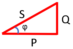
Apparent power is also equal to as per the below formula (refer to figure 1):
Apparent power S = √ ( P2 + Q2 )
Figure 1 shows the diagram of P, Q, and S power.
Now if the load is only a resistor and reactive power (Q) is zero, then apparent power is equal to active power “P”.
If Q = 0, then
S = V X I = P
If the load is only the inductor or capacitor and no active power (P is equal to zero). Then the apparent power is equal to the reactive power “Q”.
if P = 0, then:
S = V X I = Q
Now we will discuss the power factor.
What is the power factor
Power factor is defined few ways
1 – The power factor is equal to the ratio of the active power and apparent power
Power Factor = P/S
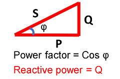
2 – The power factor is also equal to the cosine of the phase angle between voltage and current. So if this phase angle is φ then
Power Factor = Cos φ
The power factor is the ratio of active power and apparent power. It is also equal to the cosine of the phase angle between voltage and current.
Difference between power factor and reactive power
As per the above discussion, we know that reactive power is the power flow in the reactor or capacitor.
But the power factor is the ratio of active power and apparent power.
As apparent power depends on the active power and reactive power both, So power factor depends on active power and reactive power both.
So the main difference between power factor and reactive power is that power factor is just a ratio and depends on the active and reactive power both, while reactive depends on the inductive or capacitive load. if active power is changing then the power factor will change even if reactive power does not change.
Examples of change in power factor and calculation.
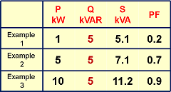
I will consider 3 examples for power factor calculation. The reactive power (Q) remains the same in all three examples, but active power is different.
Example 1
If reactive power is 5 kVAR, and active power is 1 kW, then the power factor will be 0.2 as per figure 2.
Example 2
Now if reactive power is still 5 kVAR and active power is 5 kW, then the power factor will be 0.7 as per figure 2.
Example 3
Now if reactive power is still 5 kVAR and active power is 10 kW, then the power factor will be 0.9 as per figure 2.
You can see above that even if reactive power is fixed, but power factor is changing depending on active power.
If reactive power remains the same the active power increases then the power factor improves. And we say the power factor is good now even if no change in reactive power.
Reactive does not depend on the power factor, but the power factor depends on the reactive power.
Summary
So as discussed above, there are the following differences between power factor and reactive power:
- Reactive power depends on current and voltage in the inductive or capacitor load.
- Reactive power does not depend on resistor load.
- The power factor depends on the reactive power.
- The power factor is the ratio of active power and apparent power.
- The power factor is also equal to the cosine of the phase angle between voltage and current.
- Power factor depends on resistor load as well as on an inductor or capacitor load.
- The power factor may change for a fixed inductor load depending on the resistor load.
Extra knowledge as per experience
In the above discussion, we have seen that power factor is a mathematical term that depends on reactive power. The power factor is poor due to this reactive power.
This reactive power needs to be reduced to improve the power factor.
When we say power factor correction means that we have to reduce this reactive power.
So this reactive power is more important than the power factor.
Suppose reactive power is 0.1 kVAR and active power is also 0.1 kW. The power factor will come to 0.7 as per calculation.
So you can observe that, if you see the power factor, then it looks very bad system as the power factor is very low, about 0.7. So power factor compensation should be done.
But if you see reactive power, it is just 0.1 kVAR. This small power will not affect the system, so compensation is not required. No need to improve the power factor.
So reactive power is a more useful indication of the power system quality than the power factor. So we concentrate on the reactive power and not on the power factor,
However, for a small system, we always say that power factor correction equipment is required.
However, for a big system, we always concentrate to reduce the reactive power. As this reactive creates all the problems.
I designed many control systems for power factor improvement for rating up to 100 MVAR for steel plants having a load of 100 MW. But the control system measured and corrected reactive power, and not the power factor except for the small size of the equipment.
A power factor indication meter will be there for indication, but control will be only for reactive power in a big system.
Reactive power in resistor-type load
There are rare cases when the current flowing in the resistor itself behaves as a reactive power.
These are HVDC converter stations and also unbalanced active load in a 3-phase supply in steel mills. In both cases, reactive power flows in the system if measured, even if the load is basically an active load or resistor. Further discussion on this topic is not within the scope of this article.
For further detail watch the following video:

Hope that you enjoyed reading an article on the difference between power factor and reactive power.
Keep learning and reading open circuit CT transformer.
Also, read the CT PT transformer difference.
Continue reading Energy saving-tips.
Further, read about AC or DC which is more dangerous.
Must read on How to become a topper in college.
About the author – G K Agrawal B.Sc and B.Tech (from HBTU Kanpur), Retd. Sr DGM Design (BHEL), the inventor of patents, has lifelong industry experience in the electrical and electronics design field of R&D. He worked for BHEL. He shares his experience and knowledge on blogs and YouTube. Read the profile here.

Very nicely explained.