
In this post, I will explain “how the SMPS transformer works” or the switching transformer concept works. I will also discuss the core type, losses, Litz winding type, flux generation, and reason for the small size and less weight of the SMPS transformer and differences from the power transformer.
I will tell about using 1952 numbers of transformers used in one of our projects.
The table of content of the article is as follows:
What is and how does the SMPS (switching) transformer works
The SMPS transformer is a special transformer that works on the concept of switching it at high frequency. The high-frequency operation of this transformer reduces the cost, size, and weight of the SMPS transformer. It also makes the power supply compact and efficient.
The SMPS transformer is also called a switching or switch-mode transformer. We call it a switch-mode transformer, as ON OFF action of a switch is required to operate this transformer.
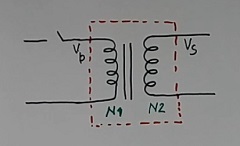
Sometimes we call it to pulse transformer also. Refer to a switch in primary winding in figure 1.
This switch operates at a high frequency. The advantage of this kind of arrangement is that the transformer becomes small in size. The weight of the transformer also becomes less and hence the cost.
We can design the SMPS transformer and it works based on these two energy mode concepts.
No energy storage mode
In this mode, the transfer of energy from primary to secondary takes place like a power transformer. We do not store energy in the transformer.
That time VS / VP = N2 /N1 ( as per figure 1)
Energy storage mode
In this case, first, we store the energy in the transformer, then we transfer the energy to the load. In this mode, the voltage ratio is equal to the turns ratio formula may not be valid.
How Inductor current flows in the SMPS transformer works
This understanding of this concept is very important to understand how the SMPS transformer works.
We will learn this concept using two diagrams in Figures 2 and 3.
First, refer to figure 2. The circuit has only a resistor in the circuit.
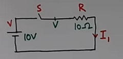
If we make the switch “S” “ON”, then the voltage at point V in figure 2 will increase suddenly. And the electric current I1 also will increase immediately to full value. (refer to figure 3).
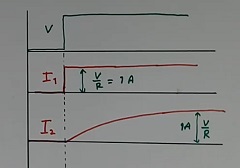
If the voltage is 10 volts, and the resistor value is 10 ohms, then 1 amp electric current (I1) will flow in the circuit.
Now, refer to figure 4. This circuit is similar to circuit 2 as above. But this circuit has a resistor and inductor both in the circuit.
Whenever we make the switch “S” ON. The current I2 will flow in the circuit as per waveform I2 in figure 3 above. Note that the current is increasing slowly.
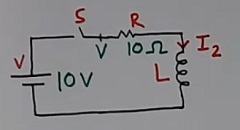
The maximum value of the current still will be 1 amp as in the earlier circuit without an inductor. But now, the inductor is making the current increase slowly.
This slow change in the current due to the inductor is the basic concept on which the SMPS transformer works.
Voltage current flux generation sequence
The learning of voltage current flux sequence will help to understand how SMPS transformer works.
Refer to the circuit in Figure 5. It has a transformer with an open secondary (no load).
Now, if we apply a voltage in the primary, the current flows in the primary winding. And this current rise slowly due to an inductor in the primary winding (exactly as in the circuit of figure 4).
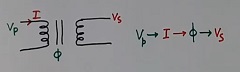
So VP generates the current “I” (IM) in the primary winding. Now we already know that the current generates the flux. So flux will also be there in the core. And this flux flows in secondary winding also, as the core is common.
Note: Above current is considered magnetizing current (part) only
Now as this flux is changing, so change in flux in the secondary will induce a voltage in the secondary winding.
So the sequence is — Voltage – current (magnetizing current) – flux – change in flux – induced voltage in secondary.
This sequence will help to understand the function of the switching transformer, and how the SMPS transformer works, in the next para.
Why is SMPS transformer small in size and weight?
To understand that how the SMPS transformer works with a small size and weight, we will learn the concept of flux formation in the SMPS transformer core.
Refer to figure 6. The circuit has a transformer with secondary open (no load connected). And give a square waveform at the input of the primary winding.
Note that, earlier we applied step voltage in figure 3. But now we are using a square waveform in figure 6. And the square wave is like switching ON and OFF the input DC voltage at high frequency.
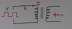
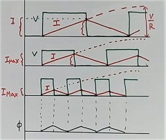
The voltage and current waveform are shown in figure 7 (see waveform A). The green (looks like black) is a square wave of voltage at the input. The red color waveform indicates the current flow in the primary winding.
Note that the current (magnetizing part of the current) will reach the maximum value after some time if we give the continuous voltage DC at the input. See the dotted current line in waveform A).
However before it reaches the maximum value, we remove the voltage at the input. So the current will start reducing without reaching the maximum value.
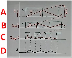
The faster we make the voltage zero at the input again, the lessor the peak current flows in the circuit. This is due to less time available to increase the current.
And then the current will start reducing due to no voltage at the input.
So, If we reduce the voltage pulse width (which means high-frequency voltage) as in waveform B. The peak value of the current will be less further, as the time available is less for the increase in the current.
And if the magnetizing current is less, then flux also will be less. Refer to waveform D in the above figure. The flux peak is very less.
So, the SMPS transformer works with a small flux in the core.
Advantage of less flux due to high frequency
We have discussed above that the flux in the core will be less at high-frequency current.
And less flux requires a smaller size of the core. Exactly this concept is responsible for the small size of the SMPS switching transformer.
Higher the frequency, the less time available for the current to rise in every cycle, and so less peak current. hence less flux and a small size of the core.
Small core size
Now, refer to figure 8 now. The core size is shown for low and high frequencies. The fL means less frequency and fH means the high frequency of the voltage.
If the frequency is high, then the time period will be less as T = 1/f. Less time means less current rise in winding, so less flux and a smaller core. So core diameter is smaller for the higher switching frequencies.
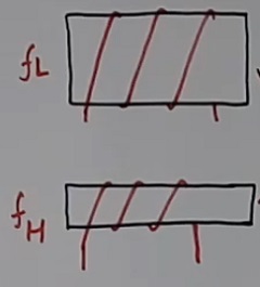
And this way, the SMPS transformer works with the very small size of the core.
Difference between SMPS switching transformer and power transformer
There are the following differences between SMPS transformer and power transformer characteristics.
Power transformer characteristics
- Input and output voltage is sinusoidal in nature
- It operates at a low frequency
- Generally, it has more power rating than the SMPS transformer
SMPS switching transformer characteristics
The SMPS transformer works on the basis of the following characteristics
- Inputs and outputs in the SMPS transformer are nonsinusoidal.
- SMPS operates at a high frequency.
- The power rating of the SMPS transformer is less compared to the power transformer.
- The core material has high ohmic resistance in the SMPS transformer.
- The BH curve area is small to reduce hysteresis loss.
- The value of magnetic permeability (μ) is less.
- The core material is brittle and fragile.
- The size is smaller than the power transformer for the same power rating.
Losses concept in the SMPS transformer
There are two types of losses in the switching transformer.
- Winding Cu loss
- Core loss
The above two types of losses are explained below. Understanding these losses is important to understand, how SMPS transformer works.
Winding copper loss I2 R
The value of the losses in copper is equal to I2 R. However this formula is valid for the DC. There is a small deviation in the case of the AC.
If the frequency of the AC supply is high as in the SMPS transformer. Then the effective resistance of the wire is more than normal, as the electric current does not flow in the whole area of the conductor.
There are two reasons responsible for the increase in the effective resistance of the conductor.
- Skin effect
- proximity effect
Ohmic loss due to skin effect
It is due to the eddy current induced in the conductor by the current flowing in the conductor itself.
In simple terms, generally current tends to flow more in the outer portion of the conductor and less in the center at higher frequencies. This is called the skin effect.
So loss becomes more as the effective available copper area is less at high frequency.
Refer to figure 9. The top image is of a conductor. The bottom image is the cross-section area of the conductor.
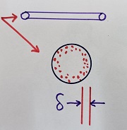
The red color points show the concentration of the electrical current flow. The current is not flowing in the full area of the wire due to the skin effect. So effective resistance is more here.
The current density is much more near the outer side of the wire. And the width of the portion of the wire for most of the current flow is called a delta.
As the SMPS transformer works at high-frequency electric current, so this problem is more in the SMPS transformer. And so the concept of the skin effect is more important here.
Ohmic losses due to proximity effect
If there are two wires very close to each other. And the current is flowing in both of them. And suppose the direction of the current flow is the same on both conductors. Referring to figure 10.

Then the current in the conductor sifts to the outer side of the conductor as per the current direction. The red dots show the concentration of the current flow in the conductor.
This is called the proximity effect in the current carrying conductors.
So again current flows in less copper area of the wire, so losses are more.
This problem is everywhere but is more in SMPS due to the high frequency of the current. So SMPS transformer works at a high-frequency current.
Core losses
There are two types of core losses in switching transformer
- Hysteresis losses in the core
- Eddy current loss
Hysteresis losses in the core
Refer to figure 11. It shows the BH curve. Hysteresis losses are losses in the core due to work done or energy consumed during one complete cycle (shown in red color) of the magnetism of the core as per the BH curve.
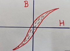
These losses are more for high-frequency current, as the number of complete cycles will be much more with the high-frequency electrical current.
Further, to reduce this loss, the internal area of the BH curve should be narrow or less. So the SMPS transformer works with a core material of the narrow BH curve area. As it is more suitable for using the high-frequency AC input concept in the SMPS transformer.
The Eddy current losses in the core
This is due to locally induced emf in the core due to flux flowing in the core. Note that this is different from the induced voltage generated in the secondary of the transformer.
Further the current also will flow in the core due to this induced voltage in the core itself (not the winding wire). We call it the eddy current.
So the mechanical design of the core should be such that, the core should have a high resistance path in the eddy current path to reduce the current. Then only the SMPS transformer works properly.
The type of windings in the switching transformer
There are four types of wires are used in winding over the core in the SMPS transformer design concept.
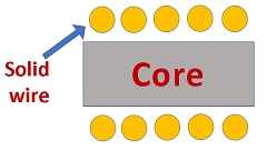
A – Solid wire
This is a normal single-strand copper wire. Refer to figure 12. The yellow color indicates the solid wire winding over the core. This is a normal winding method.
B – Litz wire
We know that at high frequency, the current concentrate at the outer side of the wire, and effective resistance becomes more. So more heating will be there in the SMPS transformer due to high frequency.
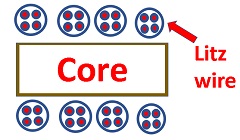
To solve this problem, we use the Litz wire. Refer to figure 13. This wire has a group of many wires (red color) with insulation above this (black color around red). This way surface area of the wires becomes more.

It shows the Litz wire winding around the core.
Now refer to figure 14. There are 4 turns of Litz wire in the figure. It is just, for example. Actual turns may be many more.
C – HV wire
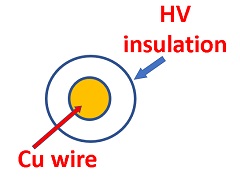
Figure 15 shows the high-voltage wire. There is a high voltage insulation over the copper conductor.
D – Cu foil
In this type, we use copper foil in place of the wire for winding. It is a plane flat sheet of copper. So it has a very large surface area. Refer to figure 16.

This copper foil is used for winding purposes in place of the wire in the case of the SMPS transformer sometimes, such that the SMPS transformer works properly at high frequencies.
The shapes of the core in the SMPS transformer
You can see three types of shapes of the core in figure 17. Generally, the SMPS transformer works with the uses of these core shapes, which are as follow
- E shape
- ETD shape
- Torodal core shape
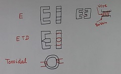
Now, see the bobbin at the top right side in figure 17. This bobbin fits over the middle arm of the E shape core.
To complete the core, we can use one E shape and one straight core, or two numbers of the E cores (shown at the top left of the bobbin).
The last toroidal type has a round shape. It is very good. It does not generate EMI interference also. The losses are very less in this type of core as there is no corner.
But the making winding over the toroidal core is a little difficult, but this type of SMPS switching transformer works perfectly.
Figure 18 shows a small-size SMPS transformer. It is made using the E-type core.

Extra knowledge as per experience
In one of our HVDC experimental projects, I used about 1952 numbers of the pulse transformer (a concept similar to the SMPS transformer). We call it a pulse transformer, as just a very few voltage pulses are applied across the transformer in every cycle (50 Hz AC).
A large number of transformers were used to give a gate pulse to the 1952 thyristor in the converter and inverter.
Then, the use of an isolation pulse transformer solved my many technical problems in triggering such a large number of thyristors for a 100 MW, 100 kV HVDC link.
This pulse transformer used by us was of the high voltage type with few kV ratings.
For further knowledge watch the following video
Further, read what is potential transformer
Also, read what is Current transformer.
Further, read Why and how power factor correction
For knowledge on open circuit, transformers read how to use open circuit transformers.
Also, read How to check a transformer at home with a multimeter?
I hope that you enjoyed the reading article on the topic “How SMPS transformer works”
If you like the article then subscribe to Youtube to get further knowledge
About the author – G K Agrawal B.Sc and B.Tech (from HBTU Kanpur), Retd. Sr DGM Design (BHEL), the inventor of patents, has lifelong industry experience in the electrical and electronics design field of R&D. He worked for BHEL. He shares his experience and knowledge on blogs and YouTube. Read the profile here.

Pingback: Why is the electrical transformer rating is in KVA - G K Agrawal