The snubber circuit finds application in power electronics and switching devices. We will discuss in this post, what is snubber circuit, and what are the applications of a snubber circuit.
What is a snubber circuit?
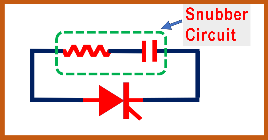
The snubber circuit is a series connection of a resistor and a capacitor. This resistor-capacitor combination is connected, generally in parallel to a power device like a MOSFET, thyristor etc.
There may be other types of components also called snubber circuits, but mostly RC combination is referred as snubber circuits.
Refer to Figure 1. The snubber circuit consisting of the resistor and capacitor is connected across the thyristor in this example.
Even if it looks like a simple circuit, it is generally an essential part of the power circuit with power devices.
This R and C combination provides a low impedance path at lower frequencies.
It also acts as a low impedance connected in parallel and draws a very small current at low frequency like at 50 hz or 60 hz.
The purpose and function of this circuit become clear in next para during discussing applications.
Applications of the Snubber circuit
The snubber circuit finds many applications in power circuits as follows:
Voltage sharing
If we connect many power devices like thyristor or MOSFET in series for AC application to make it high voltage circuit. Then this RC circuit helps proper voltage distribution across all devices.
If we do not connect this snubber circuit, the voltage distribution across all devices will not be equal.
In such cases, a few devices like MOSFET or thyristor will have more voltage and it will fail.
Latching current in thyristor
A proper design of this circuit helps in creating a latching current faster during switching ON. so it reduces the the risk of less gate pulse width.
A detailed explanation of this is given in the video (link at the last of this video)
Snubber circuit with inductor – applications
Now refer to Figure 2. Many times a small value inductor is connected to a series of devices.
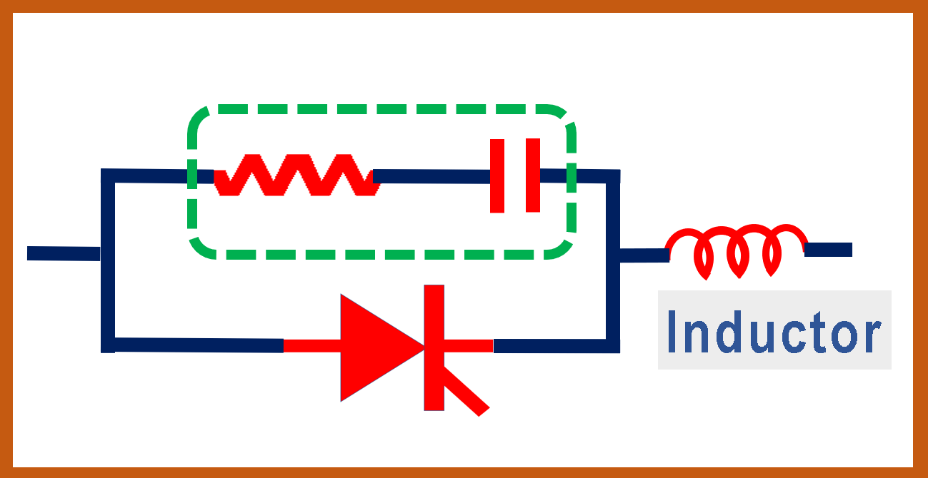
This kind of arrangement helps in the following ways:
- During the high voltage transient like in switching impulse, this reduces the effect of the high voltage across the devices.
- This inductor also helps in reducing di/dt current. It is explained in detail in the video.
Extra knowledge as per experience
In many conditions, a DC voltage also appears across devices even if we apply only AC.
For example, in the case of a 3-phase bridge rectifier, or any AC to the DC conversion circuit like VFD, HVDC ect, The DC voltage will also appear across the devices.
The snubber circuit will not distribute DC voltage evenly across all power devices in series. This is because the snubber circuit has a capacitor also.
So almost always, another resistor is connected in parallel to the snubber circuit to take care of the DC voltage distribution problem.
If you like to watch the video then watch the above to learn in detail in English and Hindi both as follows:
I hope that you enjoyed reading the article on the “Snubber circuit and its applications”.
If so, then subscribe to my YouTube channel.
Also, read How to use an open circuit current transformer.
Continue reading How Bullet Train Works.
Further, read the CT and PT transformer differences.
Also, read the Differences between DC and AC clamp meter.
About the author – G K Agrawal B.Sc and B.Tech (from HBTU Kanpur), Retd. Sr DGM Design (BHEL), the inventor of patents, has lifelong industry experience in the electrical and electronics design field of R&D. He worked for BHEL. He shares his experience and knowledge on blogs and YouTube. Read the profile here.