
It is very important to do earthing of the neutral of the substation transformer. In this post, You will learn, what are the problems if there is no earthing in the transformer.
I will explain, how the high voltage comes in the transformer without earthing during fault. I will also suggest a very simple DIY project to learn problems.
Why substation transformer neutral earthing
“The main purpose of the earthing of the Neutral of the Substation transformer is to limit the high voltage during fault or noise, and also for safety”.
We will discuss this in detail.
Substation transformer with neutral earthing
Refer to figure 1. This circuit shows a substation transformer with neutral earthing. The primary of the transformer is in a delta connection. The primary side is connected to the high-voltage incoming three-phase AC supply.
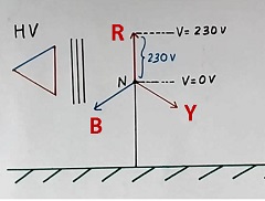
All three secondary windings are connected in star connections. The neutral point of the secondary winding of the substation transformer is connected to the earth. The phase voltage is 230 volts (for example) as in houses. And line-to-line voltage (say between R and Y points) will be root three times, about 398 volts.
But if the transformer is for some other purpose then this voltage of the secondary may be high. For example, If the phase voltage is 10kV then the line-to-line voltage will be 17.3kV.
As the neutral is connected to the earth, the voltage of the neutral of the transformer is zero volts. And as phase voltage is 230 volts, the voltage of points R, Y, and B will be 230 volts equal to the phase voltage.
Substation transformer without neutral earthing
Now refer to Figure 2. Here neutral of the transformer is not connected to the earth. So the voltage of the neutral is not defined and it may not be zero. We call it floating neutral.
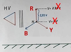
The phase voltage (say between R and N) is still 230 volts. Now as the voltage of neutral is not known, the voltage of points R, Y, and B also can not be defined.
Further as neutral is floating, the high voltage will come at the neutral and also at all the three R, Y, and B points during switching or lightning transients.
Voltage measurement problem
Generally, voltage-measuring instruments or potential transformers are connected to the R, Y, and B points with respect to the earth, especially in high-voltage applications. They will not measure voltage correctly if the transformer neutral is floating and has no connection with the ground.
No high voltage in the substation transformer with earthing of the neutral
Now let us see Figure 3. Here neutral is connected to the earth. Further, suppose there is a fault between Y and the earth. We call it line to ground fault.
As phase Y has the line to ground fault, heavy short-circuit electric current flows in phase Y through the earth and is neutral. However, points R and B will not see any high voltage.
Hence, the earthing of the neutral of the Substation transformer is important in any electrical power system. This neutral is also connected to the neutral wire for the loads, but with a separate neutral wire. An electric current in the load flows through this separate neutral wire and not through the earth.
How high voltage comes in substation transformer without neutral earthing
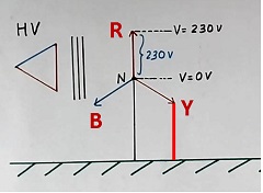
Figure 4 shows a circuit with the neutral of the secondary of the transformer is not connected to the earth.
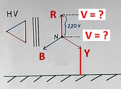
Now if the line to ground fault comes at point Y. Then the voltage of point Y will be zero voltage. And voltage of neutral will become 230 volts (equal to Y phase voltage).
Further, the voltage between R and Y is 398 volts (line-to-line voltage), and the voltage at point Y is zero. So the voltage at point R will become 398 volts (equal to the line-to-line voltage between R and Y phases).
So in this case, the voltage at point R is 398 volts as compared to the earlier 230 volts. and we call it high voltage.
If the phase voltage is 10 kV, then the voltage of point R will be 17.3 kV (equal to the line-to-line voltage between B and R)
So high voltage will come during fault if the neutral point is not tied or connected to the earth in the transformer.
This high voltage may damage the transformer.
Further, all equipment connected to phase R (or phase B also) will get high voltage and will be damaged.
Conclusion
As discussed above, if the neutral wire of the substation transformer is not connected to the earth, then there will be the following problems:
- The problem in voltage measurements for indication and control purposes
- High voltage transients during switching and lightning transients
- High voltage during faults
- Damage to equipment during faults, due to high voltage
- Safety problems due to floating points
Extra knowledge as per experience
We discussed line to ground fault above. This is because the line to the earth or line to the ground fault is one of the most common faults.
The earthing of the neutral of the high voltage substation transformers affects the cost of the transformer also. In case, we want the option of not connecting to the ground and want all six terminals of the three windings of the transformer, then the cost of the transformer will increase.
This is because the manufacturer has to design all six terminals for high-voltage insulation.
We may need all six terminals of the three windings of the high-voltage transformer for flexibility purposes, especially for testing applications in the test lab.
Do it yourself experiment – DIY
Take a simple electrical step-down transformer of 230/12 volts or something similar. Now give input AC supply to the primary of the transformer. Do not connect any wire of the secondary to earth (generally it is like that).
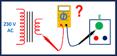
Refer to Figure 5. Now measure the voltage between any terminal of the secondary winding of the transformer and the earth with a multimeter. (Do not touch any terminal of the secondary winding). The multimeter may not measure the voltage properly.
If you like videos and want to learn more then watch the following video:
I hope that you enjoyed reading this article on the topic “Substation transformer neutral earthing”
If so, then subscribe to my YouTube channel.
Further, learn “How to use open circuit CT transformer”
Also, read “Difference between neutral and earth”
Read AC or DC which is more dangerous.
Continue reading The advantages and disadvantages of the autotransformer.
About the author – G K Agrawal B.Sc and B.Tech (from HBTU Kanpur), Retd. Sr DGM Design (BHEL), the inventor of patents, has lifelong industry experience in the electrical and electronics design field of R&D. He worked for BHEL. He shares his experience and knowledge on blogs and YouTube. Read the profile here.
Very nicely explained every point in detail.