
In this post, you will learn the various differences between CT and PT transformers like functions, inputs, outputs, connections, construction, short circuit, open circuit, accuracy, etc.

As this is a big article, the list of content is included. The contents of this post are as follows
Difference between the CT and PT transformers
The current transformer (CT) and potential transformer (PT), both the transformers basically have an iron core and a few windings over the core. And they may appear to be similar components, but they are quite different.
The basic difference between CT and PT transformers is that the CT transformer is used for the current measurements and the PT transformer is used for the voltage measurements.
Further, we step down the current level in the case of the CT transformer applications. As the primary current is more, we want less current in the secondary of the transformer for further use.
But we step down the voltage level in the case of the PT transformer application.
Further, the CT and the PT transformers also have many more differences in functions, inputs, outputs, connections, construction, short circuit, open circuit, accuracy, number of windings, number of turns, etc.
CT and PT transformers – symbol difference
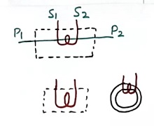
The symbol of the current transformer (CT) is as per figure 1. The dot shown on the two windings indicates the polarity of the input and output waveforms.

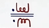
The symbol of the potential transformer (PT) is as per figure 2. The dot shown in the winding indicates the polarity of the input and output signal waveforms.
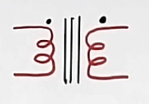
But sometimes, the symbol of CT is used as shown in figure 3. This symbol looks similar to the PT symbol in figure 2.
In this tutorial, I will use the symbol for the CT as per figure 3.
CT and PT Connection diagram – the difference
The connection method of the CT and PT transformer is also different.
Refer to Figure 4 for the connection diagram. The primary winding of the CT transformer is connected in a series of loads. The load is indicated here as a resistor in the circuit.
So the full load current flows in the primary of the CT transformer.
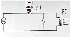
But, the primary winding of the PT transformer is connected in parallel to the voltage to be measured. This is as per figure 4. The resistor shown in the circuit is the load here.
The PT is connected in parallel to the load in the above circuit. This is because we want to measure the voltage across the load resistor in this application. And full system voltage will come across the primary of the PT transformer.
PT transformer circuit for current measurement
Suppose there is a resistor RS as per figure 5. And we want to measure the voltage across this resistor RS. Then we connect the primary winding of the PT across this resistor RS.
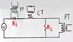
You can see, that, the PT transformer primary is connected across the primary in the above application as per figure 5.
In fact, this method makes the measurement of current possible using PT in a few cases. The value of the resistor RS will be very small in such cases.
The voltage across RS divided by the resistor value RS will be equal to the current flowing in the circuit.
Difference between the construction of the CT and PT transformer
In the case of the CT transformer, the turn in the primary winding is less than the secondary winding. Sometimes primary winding has just one turn.
While in the case of the PT, the turns in the primary winding are more than in the secondary winding.
CT transformer without any primary winding
Further bar type CT does not have the primary winding at all. A single bar itself acts as a single turn of the primary winding. Refer to figure 6.
The core will be round type (third image in figure 6). Only secondary winding will be there.
Sometimes even the bar will not be there (refer to 2nd image in figure 6). The load wire passing from inside of the core itself acts as a single turn of the primary winding.
In the case of the PT transformer, the primary winding is a must.
The inputs of CT and PT transformers difference
In the case of the CT transformer, the voltage across primary winding will be very less, generally only a few volts.
While in the case of the PT transformer, the voltage across the primary winding will be more. It may be very high in some cases.
Range of the CT and PT
The CTs are designed for the wide range of the current at the input. For example, the input of a 1000 amperes CT may vary from zero amperes to 10000 amperes. (Read about 10000 amperes of electric current in the next para).
While PT is designed for a limited variation and range of voltage at the input.
System short circuit problem
The system short circuit level is very important in the CT transformer design.
In case of faults, a 1000 amperes CT may have 10000 amperes current flow in the primary (and hence flux in the core) for the short time during a system short circuit. The CT should be able to take this current without any damage to it.
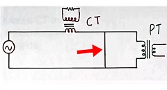
Refer to figure 7. A short circuit (red arrow) will increase the current in the primary to a very high value. The CT transformers are designed for such conditions.
However, in the case of the PT transformer, such a problem is not there. As there will be no over-voltage across the primary of the PT transformer.
The outputs of CT and PT transformers – differences
The output of the CT transformer is not kept open. While the output of the PT transformer can remain open.
Another difference between the CT and PT transformers is that, In the case of the CT transformer, a low resistive load is safe, and a high resistive load is not safe.
But in the case of the PT transformer, a low resistive load at the output is not safe, but a high resistive load is safe.
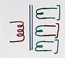
Refer to figure 8. This PT has many (three) output secondary windings. But the CT transformer generally has only one output. However, The CT transformer may have many secondary windings in rare cases.
Output voltage variation difference in the CT and PT
In the case of the CT, output voltage across the secondary changes too much with load resistor variations. A 100 percent increase in the resistor value will increase the voltage by 100 percent.
However, in the case of the PT, the change in output voltage is not so much. For a 100 percent increase in resistor, the variation in output may be less than 10 percent.
Short circuit in the output of the CT and PT
A short circuit in the output of the CT does not create any problems.
However, the short circuit in the output of the PT is not acceptable, The PT may burn out.
Accuracy and impedance difference between CT and PT transformers
Accuracy in the CT and PT
In the case of the CT transformer, it is difficult to maintain accuracy due to a wide variation range in the primary current.
However, it is easier to maintain accuracy in the case of the PT transformer, as voltage variation is less.
The impedance of CT and PT
Another difference between CT and PT transformers is that,
In the case of the CT transformer, the impedance of the CT is not that important.
However, in the case of the PT transformer, the impedance of the transformer is more important.
Extra knowledge as per experience
We always talk that the secondary winding of the CT can not be kept open.
However, in one of the projects, we used the CT transformer with an open secondary.
The CT with the open secondary – application
This is a very special application of the CT with one open secondary winding in one of our projects.
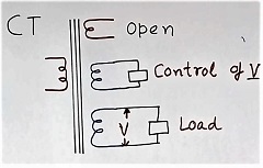
Refer to figure 9. The CT transformer has one primary winding in the figure. This is for explanation only. Our CT was bar type without any primary at all.
It has three secondary windings. The 1st winding in the secondary is open.
One of the secondary winding (third winding in figure 9) has the load across this, so nothing to explain here.
The 2nd secondary winding (middle secondary winding in figure 9) has a control circuit to limit the voltage across this winding.
For a detailed explanation of the current transformer with an open secondary, read the article post on “CT transformer with the open secondary“.
We used this extra open winding in the secondary of the CT transformer as a spare for future use. However, we never used that extra open winding of the CT.
But we continued to keep one extra winding in the CT for no use in our all subsequent projects.
The necessity of the change in design
In the industry, we do not try to change the working and proven design until it is necessary. We only modify and concentrate on nonworking designs as for as possible. However, this does not stop us from doing incremental product improvements.
Further removal of extra winding neither reduces the cost nor the size of the CT.
In fact, the removal of the winding may increase the cost of the CT transformer. This is due to the high cost of the type Tests to be performed again.
The use of the CT and PT transformer
Even, though there are many differences between the CT transformer and the PT transformer. But the fact is that both are transformer and follows all the principles, rules, and formula of the transformers.
The CT transformer is nothing but a very low-voltage PT transformer or voltage transformer.
If we follow the limitation of voltage and current of various windings in the CT or PT, we can use them as we want. A CT can be used as PT. And a PT can be used as a CT. But the error will be more in such applications.
But such use is very limited due to the low voltage in the CT transformer and high voltage in the PT transformer. And also accuracy is the problem in such arrangements.
We have used CT as a PT for experimental purposes in our lab.
If you want to be more clear about this, then you can do such an experiment, but keep the voltage in different winding limited to the rating of the windings.
In fact, a transformer can be used in different ways. For detail watch my video on the topic, How to use a transformer in 6 different ways.
However, the above video is only for learning purposes as a concept. This experiment should be done only under expert supervision.
Further for detailed information watch the video CT PT transformer difference
Further, read also the post on the What is potential transformer
Also, read the article on how the current transformer works
For more knowledge read about the SMPS transformer
Continue reading the Advantages and disadvantages of the autotransformer.
I hope that you enjoyed the article on CT and PT transformer differences.
If so, then subscribe to my YouTube channel.
About the author – G K Agrawal B.Sc and B.Tech (from HBTU Kanpur), Retd. Sr DGM Design (BHEL), the inventor of patents, has lifelong industry experience in the electrical and electronics design field of R&D. He worked for BHEL. He shares his experience and knowledge on blogs and YouTube. Read the profile here.

Very detailed explanation given.