
In this post, I will explain what is an optocoupler, and how an optocoupler works. I also will explain the applications, types, and a circuit diagram explanation with signal, and also experience-based knowledge of the optoisolator.
Nowadays optocoupler finds use almost everywhere in electronics and power electronics circuits.
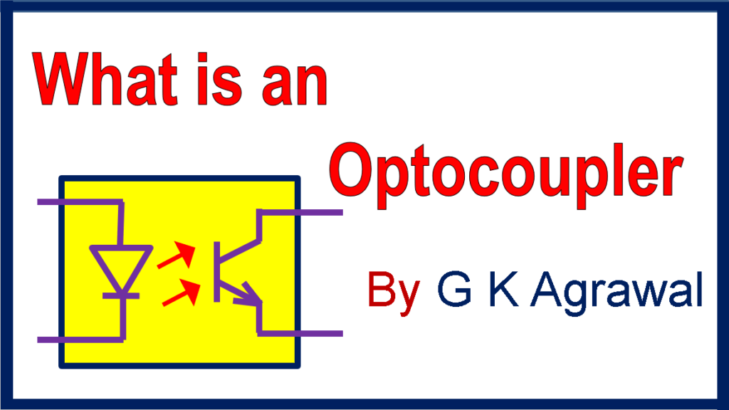
What is an optocoupler?
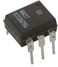
An optocoupler is an electronic semiconductor device that interconnects two separate isolated electrical or electronic circuits using a light-sensitive optical interface. It is also called Photocoupler or Optoisolator.
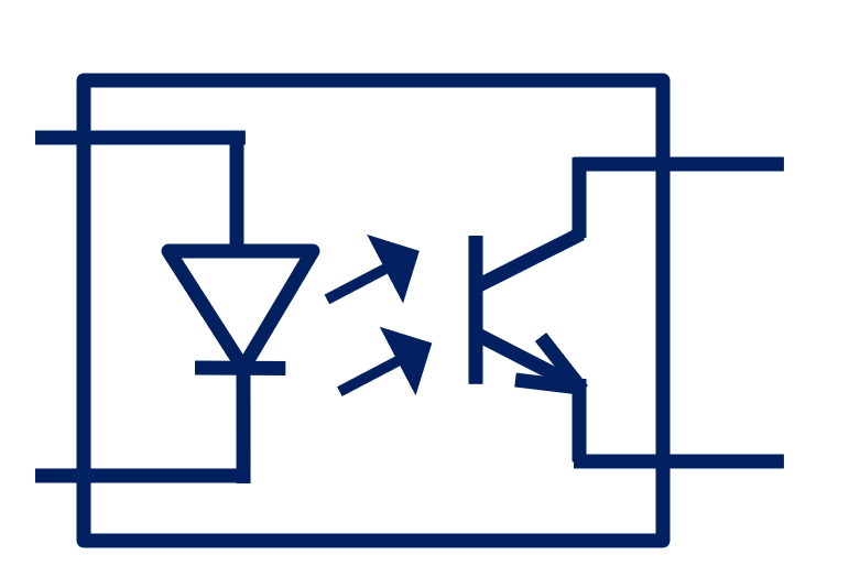
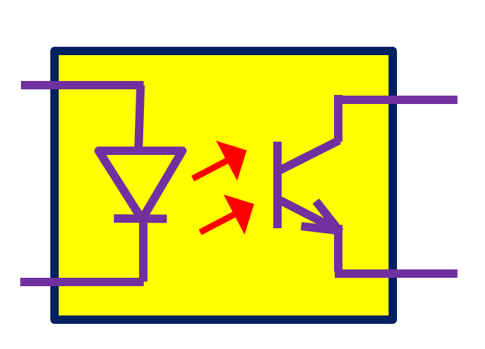
The diagram in figure 1 shows the simple symbol of a phototransistor-type optocoupler without a base of the phototransistor. This is a common type of optoisolator.
How optocoupler works
As electrical current flows through the input LED, the LED emits light. This light emission takes place inside the optocoupler. This light falls on the input of the optically sensitive phototransistor of the output stage of the optocoupler.
Then an electric current results in the output of the transistor. This current transistor is approximately proportional to the LED current.
A resistor of the appropriate value limits the current flow in the input LED.
Subsequently, the current generated in the phototransistor passes through an external resistor. This voltage drop across the resistor is the output of the circuit.
The selection of components depends on the voltage level and delay in the circuit requirements.
Optocoupler circuit examples
Figure 2 shows a simple electronic circuit for signal isolation.
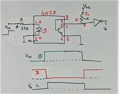
In the above circuit, Vin the input signal. A resistor of 3,3K ohms provides the current limit in the diode input of the device.
The output current of the IC flow through a 10K ohm resistor.
Signal “B” is the output of the optocoupler circuit. This is an inverted signal.
Then, this inverted “B” signal becomes a normal signal with the help of a “NOT” gate.
Further, the waveform Vo or signal ‘C” in the above diagram indicated the normal output.
The base of the phototransistor may be connected to the emitter (pin 4) using a high-value resistor (not shown in the circuit).
The value of the resistor connected to the collector decides the speed and sensitivity of the circuit. There is a trade-off between the speed and sensitivity of the circuit.
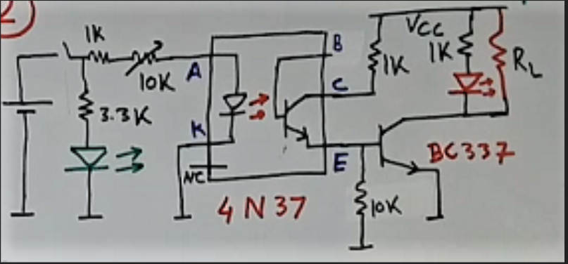
Further, figure 3 shows a circuit diagram example for the optocoupler circuit with an extra amplification stage. Transistor BC337 does the current amplification. This can be used to drive a relay also. So no digital IC gate is present in this circuit.
The optoisolator improves the reliability of the system, as it filters out some kind of electrical noise.
Types of optocouplers
The optocouplers are available in many types. A few of them are as follows
Phototransistor output type
These are as above. Darlington type has Darlington type phototransistor at the output for more current gain. This output can drive more current load like relays.
Triac output optocoupler
This type has a small photo-sensitive Triac at the output. Which can drive power Triac directly. This can be used in capacitor switching applications for power factor improvement applications. We designed a product like this for windmills for wind power applications for power factor correction.
Mosfet output optocoupler
This type has a photo-sensitive FED transistor at the output stage.
Logic output type optocoupler
This is a special type and has logic type output, say two outputs. This is to drive two power semiconductor devices like in UPS.
Applications of optocouplers
Optocouplers find wide applications in electronic and power electronic circuits and systems.
An Optoisolator gives good electrical isolation. So it is used in the measurement circuits of the SMPS. It can also be used in other circuits, wherever isolation is required.
This electronic device optoisolator also finds application as a noise filter at the input of a digital sensing circuit and digital input electronics modules. It is very good at filtering common mode noise in power plants.
An optocoupler finds use in the gate circuit of SCR devices like Triac to trigger the device. This way it becomes possible to trigger Triac at high voltage from a low voltage level signal.
Another application of the device is to amplify electronic signals also. For example, and small IC signal can be converted to a high-voltage ON-OFF signal.
Further, the input of the optocoupler is electric current based. So it connects any sensing device or electronic circuit to the switch or remote control signal. A manually controlled switch or relay contacts are the remote control signals.
For example, we used an optoisolator in many of our electronic circuit cards. This is very helpful for industrial systems. As electrical noise is more in the industry due to the presence of much high-current equipment.
Providing an optoisolator at the input stage of the switch input electronic circuits card helps to improve functionality.
They are also used widely in control applications.
Some important applications
- Industrial control
- motor control
- A/D converters
- Dimmer circuit
- Traffic lights
- Control logic
- Power switch
- DC/DC converters
- Power factor controller
- Human-machine interface
- Remote switch
- Capacitor switching with Triac
The base of phototransistor – experience-based knowledge
The circuit design of the base of the phototransistor is most critical. It affects the performance of the circuit like response time, sensitivity, and noise threshold.
If you have some problem with the circuit functioning. Then first you should review the base pin circuit.
I use different base circuits for different applications. It may be a resistor, RC circuit, nothing, or some other circuit.
But to start with you can connect a 100K ohms resistor between the base and emitter pin.
You should check for any foreign particles near the base pin on the PCB. If required, then clean the PCB surface.
Moreover, Watch the following video for detailed learning, watch an experiment and get more knowledge.
Read this information in Hindi at Optocoupler kya hai.
Further, read AC or DC which is more dangerous
Also, read for more knowledge What is a relay
Further, read Applications of Zener diode
I hope that you enjoyed reading an article on the Optocoupler.
If you like this post then subscribe to my YouTube channel, G K Agrawal
About the author – G K Agrawal B.Sc and B.Tech (from HBTU Kanpur), Retd. Sr DGM Design (BHEL), the inventor of patents, has lifelong industry experience in the electrical and electronics design field of R&D. He worked for BHEL. He shares his experience and knowledge on blogs and YouTube. Read the profile here.

Very good information