
In this post you will learn, what is a potential transformer, and also its applications. I will also discuss the specifications of the potential transformer. The test conducted on the potential transformer is also discussed.
The content of this article is as follows
What is a potential transformer (PT)?
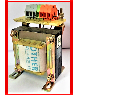
The potential transformer (PT) is a step-down transformer. Its main function is to measure the voltage accurately. So, PT provides a voltage in the secondary winding of the correct magnitude, correct phase, and correct polarity.
The potential transformer is also called PT in the short form. As basically it is for the voltage measurement or voltage reference. So the watt rating of the PT will be generally very less.
The basic requirement of the potential transformer is the accuracy of the output voltage.
We also call it an instrument transformer or voltage transformer sometimes.
PT transformer accuracy – magnitude and polarity
The basic purpose of the PT transformer is voltage measurement. So accuracy in the PT transformer is very important.
The output voltage in the PT transformer should be accurate in magnitude and phase both with respect to the input voltage.
Refer to figure 1. The correct magnitude means, that the voltage ratio of secondary and primary voltage should be correct.
The N1 is the turn of the primary winding and N2 is the turn of the secondary windings in the above formula.
The theoretical voltage ratio of secondary to primary voltage V2/V1 = N2/N1. However practically there will be a deviation in the voltage.
This deviation in voltage is due to the flux leakage, the voltage drop in the transformer impedance, other manufacturing limitations, etc. So the number of turns in the winding in the transformer is almost always different from than above formula, a little bit.
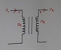
There are 2 dots in red color at the top one each in the primary winding and secondary windings. These dots indicate the polarity (Fig 1). If the voltage at the dot point is positive in the primary, then the voltage in the secondary dot point also should be positive.
Further, the transformer may have many secondary windings as per requirements. The primary winding generally will be only one.
Phase shift accuracy in the PT (potential transformer)?
Refer to figure 2 to understand the correct phase shift. The top waveform is of the primary voltage. The bottom waveform is of the secondary voltage.
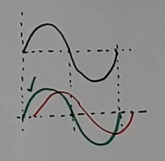
The green waveform has a near-zero phase shift with respect to the primary voltage. The red waveform has some phase shift with respect to the primary voltage, as it comes after a delay.
Secondary voltage should have a minimum possible phase shift as in the green color waveform. The delay should be as less as possible as in green waveform.
Now refer to figure 3. It shows the circuit diagram of the high-voltage PT. One terminal of the primary of the potential transformer is connected to the high-voltage point. Another point is connected to the ground.
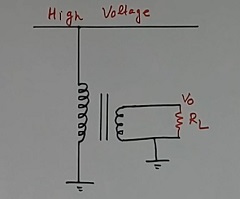
A load RL is connected to the secondary output voltage.
The basic magnetic core circuit of the PT
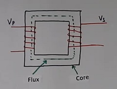
Figure 4 shows the basic magnetic core circuit. When we apply voltage Vp in the primary winding, then a flux generates in the core. And due to changes in this flux, the secondary voltage generates as Vs.
The electrical equivalent circuit of the Potential transformer
Now refer to figure 5. This shows the equivalent electrical circuit diagram of the potential transformer. I did not show the two windings of the transformer separately with isolation. The secondary winding equivalent is clubbed with the equivalent of the primary windings in series.
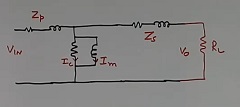
The Ic is the core loss. The Im is the magnetizing current. The Zp and Zs are the impedance of the primary and secondary windings.
The primary winding coil and secondary winding coils have some resistance. Figure 5 shows the resistance and inductance in both the primary and secondary winding equivalent circuit. Both resistance and inductance are part of the Zp and Zs impedance.
The deviation in the voltage ratio formula
If current flows in the load RL then there will be a voltage drop in the primary and secondary impedances Zp and Zs.
So, the voltage in the secondary will not be as per the formula of the voltage and turn ratio. The voltage at the secondary will be less than the theoretical value for the resistance or inductive load.
The voltage at the output of the potential transformer (PT) will be more than the theoretical value in the case of the capacitor load.
So the voltage at the output of the transformer will deviate too much from the voltage ratio formula of the transformer.
So, the manufacturers specify the output voltage at a certain define current. Generally, the secondary winding has a few extra turns than the theoretical calculation to compensate for the voltage drop in the transformer impedance.
For example, if the calculation calculates 100 turns in the secondary winding. Then they put 102 or 103 turns to compensate for the voltage drop.
This way, we get voltage ratio accuracy, especially at a particular load. The above change in the winding turns depends on the manufacturing experience of the manufacturer.
“The voltage accuracy is very important in the potential transformer, as its main aim is to measure the voltage accurately.”
The capacitive voltage transformer
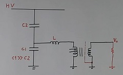
Figure 6 shows the simplified electrical circuit diagram of the capacitive voltage or potential transformer (CVT). It is a capacitor-type PT. The voltage value is reduced using two numbers of capacitors. The two capacitor works as voltage dividers.
This helps to reduce the cost and weight of the potential transformer as there is no iron core in it. However, it has some limitations in the applications.
The value of C1 is much more than the value of the capacitor C2. So the impedance of the C1 will be less than C2. Hence, we get less voltage across capacitor C1.
Further, a small low-voltage isolation transformer is used for isolation purposes. An inductor is connected in the primary of the isolation transformer for tuning purposes to get the best phase shift and voltage.
Then the isolation transformer has a shielding (dotted line in fig 6). We call it as farad shieling. This is to solve the noise problems.
The isolation transformer also has few tappings in the primary. This is to get a more accurate voltage at the output.
This type of transformer is also used as a PLC power line carrier in communications, especially in remote areas.
Applications of the Potential Transformer
The few applications of the PT transformer are:
- PT application in Voltage measurement
- PT for protection relay
- PT use in synchronization
- PT use in the control system
- PT application for isolation at low voltage
We will discuss now the above applications of the PT transformer in more detail.
1- Voltage measurements
Refer to figure 7. A PT reduces the high voltage level to 110 volts. In practice, we always used one more PT of voltage ratio 110/5 or some other. This makes it possible to use 5 volts in an electronic circuit.
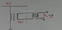
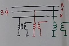
If supply is of 3-phase (it is almost always). Then we use 3 potential transformers, one each for each phase (refer to figure 8).
Further, this 5 volts output is not very accurate. So we use an op-amp type electronics circuit with variable gain (with a variable resistor) for calibration purposes to get accurate output voltage. Refer to figure 9.
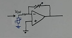
Now we can tune output voltage as per requirements. A surge protection device ( many times Transzorbs) is connected at the input of the electronic circuit to protect from the high voltage transients.
2 – PT for protection relay
Refer to figure 7 again. The output of 110 volts of the PT can be directly given to the protection relay for protection purposes as per requirements.
3 – PT use in synchronization
If we are using thyristors in the system, for example as in the HVDC or SVC system. Then we give the gate pulse to the thyristor in synchronization with the input voltage.
That time PT is useful. However, low phase error in the PT is important for this application.
4 – PT use in the control system
The PT finds use in the control system application also. In this case, gain calibration is a must as per figure 9.
5 – PT application for isolation at low voltage
Now refer to figure 6 again. A low voltage 110/5 volt potential transformer is connected for isolation purposes. This 110/5 voltage ratio may be different for different requirements.
This PT gives flexibility in design to the designer, as 110 volts is the standard voltage. Then if we want some different voltage to design a circuit, then we have to use this extra PT.
This isolation PT also finds application in CVT-type potential transformers. Refer to figure 7. This is for isolation purposes and also for flexibility in the design.
The specification example of the Potential transformer
A sample of the specification of the potential transformer is as follows
- System voltage 11 kV +/- 20%
- Voltage ratio 11 kV/ 10 V/15 V
- Primary voltage 11 kV
- Secondary voltage 10 volts, 15 volts
- Overvoltage factor 1.2 continuous, 1.5 for 30 seconds
- VA rating or burden 10 VA
- Accuracy class 0.5
- Accuracy range 80-120%, or 5-120% as per requirement
- Frequency 50 Hz +/- 5%
- Ambient temp. 70 degree
- Indoor/outdoor type as required
- terminal type as per need
- Test
- Rating plate
- Any special requirement
- Confirming to IS standard ISxxxxx.
The detailed discussion on the above point is not within the scope of this article. However, some important points are as follows
- It is difficult to make a potential transformer with high accuracy for a wide voltage range. So voltage range for accuracy is given above in the specification.
- Any special requirement is always well written in the specifications itself.
- The ambient temperature of 70 degrees is just one example and is applicable to industrial-grade transformers in India.
- The IS standard is an Indian standard. It may be different depending on the standard followed.
Test on the potential transformer
The two type tests are done on the potential transformer
1 – Routine test on the PT
The routine tests are those tests that we do on all the devices. for example, if we manufacture 100 PTs, then we do the routine test on all the 100 transformers.
These tests may be as follows
- The accuracy test for voltage ratio
- Dielectric test
- Temperature rise test
- Terminal marking
- Polarity test
- Dimension a per drawings
2- Type tests on the potential transformer
The type test is those tests, that we do on only one or 2 transformers. Some type of test may be required to be done at outside agencies. They may be expensive. We will not discuss this here to contain the article.
Extra knowledge as per experience
1 – The load at the output of the potential transformer is kept generally fixed to get more accuracy. This is because the change in the load will change the voltage level at the output.
2 – Further, if the quantity of the potential transformer requirement is large, then the temperature rise test is done only on a few samples as per mutual agreement.
3 – Generally, we tell the main application of the PT to the manufacturer. Such that they can fine-tune the PT for more important parameters.
4 – For an electronic circuit with a +/-15 volts supply, a 5-volt RMS output type PT is most suitable. A higher voltage than 5 volts may create some distortion in the output of the electronic circuits. Less than 5 volts may create more accuracy and noise problem.
This is applicable only if you use electronic circuits for calibration or further processing. 5 volts are mostly required for electronic circuits.
To get further knowledge watch Control or Potential transformer
Also, read CT PT transformer differences
You can also read the SMPS transformer concept
Also, read what is AFCI breaker
Further reading What is a windmill
Also, read what is a current transformer
I hope that you enjoyed reading this article on the topic ” what is a potential transformer and its use”.
If you like the article then subscribe to the youtube channel
About the author – G K Agrawal B.Sc and B.Tech (from HBTU Kanpur), Retd. Sr DGM Design (BHEL), the inventor of patents, has lifelong industry experience in the electrical and electronics design field of R&D. He worked for BHEL. He shares his experience and knowledge on blogs and YouTube. Read the profile here.

Very detained information